To activate this component select the Menu | Window | Dictionary tab. The Dictionary component is a special feature of the Experiments Project which interactively displays short description for each data attribute. The dictionary component is further described in the Dictionary section of the "AdvancedMiner in Practice" chapter.
By choosing Menu | Window | Lift for Tree the interactive lift chart component is activated. This component may be activated only if a tree model is open in the main editor window. For further details refer to theTree lift Section.
Log viewer is used to trace the execution of an algorithm. It can be opened by calling the Window | Log action from the main menu. Also, if the Gornik/Logger/Show Log Component on an incoming error message option is set to true (default) then the log viewer shows up whenever a new error is generated.

Log viewer messages can be selected with the mouse and their content can be copied by selecting Copy in the right-click menu.
Some messages
can be expanded displaying more detailed information. To expand or
compact a message click on the ![]() icon. Alternatively, select Expand/Pack All Messages from the component's
right-click menu to expand or compacty all messages.
icon. Alternatively, select Expand/Pack All Messages from the component's
right-click menu to expand or compacty all messages.
The content of the log viewer component can be cleared by selecting Clear All from the right-click menu.
A single line in the viewer usually has following format:
DATE TIME SOURCE - MESSAGE
where:
DATE and TIME are the date and time of the message. This can be different than the current time because the log can be generated on a remote machine.
SOURCE informs which component generated the message.
MESSAGE is the actual text of the message.
The format of log messages can still be changed in Log Viewer Settings.
The type of information displayed in the log viewer is customizable. The type of log entry is indicated by a small icon on the right:
 denotes
info. These are messages
informing the user about the progress or status of the executed
task.
denotes
info. These are messages
informing the user about the progress or status of the executed
task.
 denotes a
warning. These are messages
which warn the user about potential problems, which, however, do
not stop the execution of the task.
denotes a
warning. These are messages
which warn the user about potential problems, which, however, do
not stop the execution of the task.
 denotes an
error. These are messages
about events which caused the execution of the task to abort.
denotes an
error. These are messages
about events which caused the execution of the task to abort.
 denotes a
fatal error.
denotes a
fatal error.
 denotes a
debug level message.
These are messages about the inner workings of AdvancedMiner,
which provide very detailed information about the execution of the
task.
denotes a
debug level message.
These are messages about the inner workings of AdvancedMiner,
which provide very detailed information about the execution of the
task.
Errors, warnings and info can be displayed or hidden by clicking on the appropriate icons in the top left corner of the Log Viewer component. Fatal errors and debug messages can be turned on and off in Log Viewer settings.
Note
Please note that level settings affect only the displayed log. Turning off INFO level doesn't erase the logs. If it is turned back on messages will reappear.
You can also filter the displayed log using the text filter text box. The text filter is case sensitive. To apply the filter press enter after entering the text. After filtering the Log viewer shows only the lines that contain at least one match for the specified text.
An empty string in this component means no filtering will be applied. To remove the filter delete the text from the box and press enter.
The select text box can be used the select the first message which contains the entered text.
It is possible to customize the behavior of the log viewer and format of the displayed messages. To access the log viewer settings go to Menu | Tools | Options, select Gornik and then Logger tab.
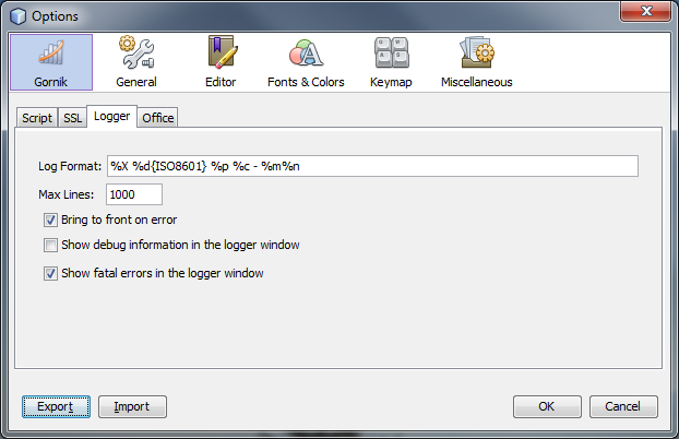
- Log format
This is a string representing the format of log messages. The default definition of Log Format is "%X %d{ISO8601} %p %c - %m%n". The following modifiers can be used to determine the log format (from JavaDoc http://logging.apache.org/log4j):
c - Used to output the category of the logging event. The category conversion specifier can be optionally followed by a precision specifier, that is a decimal constant in brackets. If a precision specifier is given, then only the corresponding number of rightmost components of the category name will be printed. By default the category name is printed in full. For example, for the category name "a.b.c" the pattern %c{2} will output "b.c".
C - Used to output a fully qualified class name of the caller issuing the logging request. This conversion specifier can be optionally followed by a precision specifier, that is a decimal constant in brackets. If a precision specifier is given, then only the corresponding number of rightmost components of the class name will be printed. By default the class name is output in fully qualified form. For example, for the class name "org.apache.xyz.SomeClass", the pattern %C{1} will output "SomeClass". WARNING: Generating the caller class information is slow. Thus, its use should be avoided unless execution speed is not an issue.
d - Used to output the date of the logging event. The date conversion specifier may be followed by a set of braces containing date and time pattern strings SimpleDateFormat, ABSOLUTE, DATE or ISO8601. For example, %d{HH:mm:ss,SSS}, %d{dd MMM yyyy HH:mm:ss,SSS} or %d{DATE}. If no date format specifier is given then the ISO8601 format is assumed.
F - Used to output the file name where the logging request was issued. WARNING: Generating caller location information is extremely slow. Its use should be avoided unless execution speed is not an issue.
l - Used to output location information of the caller which generated the logging event. The location information depends on the JVM implementation, but usually consists of a fully qualified name of the calling method followed by the callers source, the file name and line number between parentheses. The location information can be very useful. However, it's generation is extremely slow. Its use should be avoided unless execution speed is not an issue.
L - Used to output the line number from where the logging request was issued. WARNING: Generating caller location information is extremely slow. Its use should be avoided unless execution speed is not an issue.
m - Used to output the application supplied message associated with the logging event.
M - Used to output the method name where the logging request was issued. WARNING: Generating caller location information is extremely slow. It's use should be avoided unless execution speed is not an issue.
n - Outputs the platform dependent line separator character or characters. This conversion character offers practically the same performance as using non-portable line separator strings such as "\n", or "\r\n". Thus, it is the preferred way of specifying a line separator.
p - Used to output the priority of the logging event.
r - Used to output the number of milliseconds elapsed since the start of the application until the creation of the logging event.
t - Used to output the name of the thread that generated the logging event.
x - Used to output the NDC (nested diagnostic context) associated with the thread that generated the logging event.
X - Used to output the MDC (mapped diagnostic context) associated with the thread that generated the logging event. The X conversion character can be followed by the key for the map placed between braces, as in %X{clientNumber} where clientNumber is the key. The value in the MDC corresponding to the key will be output. If no additional sub-option is specified, then the entire contents of the MDC key value pair set is output using the format {{key1,val1},{key2,val2}}. See the MDC class for more details.
properties - Used to output the Properties associated with the logging event. The properties conversion word can be followed by the key for the map placed between braces, as in %properties{application} where application is the key. The value in the Properties bundle corresponding to the key will be output. If no additional sub-option is specified, then the entire contents of the Properties key value pair set is output using a format {{key1,val1},{key2,val2}}
throwable - Used to output the Throwable trace that has been bound to the LoggingEvent; by default this will output the full trace as one would normally find by a call to Throwable.printStackTrace(). The throwable conversion word can be followed by an option in the form %throwable{short} which will only output the first line of the ThrowableInformation.
% - The sequence %% outputs a single percent sign.
- Max lines
The maximum number of lines cached in the log component. After this limit is reached each added line will cause the oldest line to be removed. This settings affect all log levels.
- Bring to front on error
If this option is set to true, whenever a new error message is generated the log viewer component appears.
- Show debug information in the logger window
Selecting this option will cause debug level information to be displayed in the log viewer.
- Show fatal errors in the logger window
Selecting this option will cause fatal errors to be displayed in the log viewer.
This component can be opened by selecting Window | Projects from the main menu or by pressing Ctrl+1.
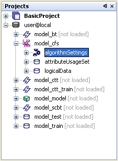
The Projects component is used to manage resources in the IDE. The most important role of this component is to provide access to the resources specified by the user. This resources are added as a new elements, called projects, and can be local directories or metadata repositories.
From the user's perspective the most important function of the Projects component is high level navigation and management of data objects (e.g. script files or metadata objects). The Projects component does not have the means to modify the internals of such objects, but offers efficient and intuitive ways of locating certain data objects or groups of data objects and performing management operations on them, such as deleting, coping or moving. The Projects component is also used to create data objects. Once a data object is located or created in Projects, it can be accessed by other tools like Properties or a custom editor associated with that object . These components are complementary to Projects, because they can change the internals of objects, but cannot modify their external properties.
The Projects component displays the opened projects using a tree structure. Each root indicates a project. After expanding a project node the user can access the resources assigned to that projects, e.g. files, directories or metadata objects.
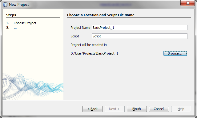
To create new project use the New Project... action in the in File menu or in the toolbar (the key shortcut for this action is Ctrl+Shift+N). The New Project... action opens the New Project wizard.

The following types of projects are available:
- Basic AdvancedMiner Project,
- Worksteps project,
- Experiments: Classification.
A Basic AdvancedMiner Project can store local directories, script files and metamodel objects.
A Classification Experiment is a project designed to support typical classification model building tasks using the logistic regression algorithm. More information about Experiments can be found in the Experiments chapter.
In the first step the user chooses one of the project types. In the second step the user chooses a name for the project and its location. It si also necessary to provide the name of the script file which will be created in the project and opened in the editor.
Every opened project can be closed with the Close Project action. This action can be called from the context menu of the project node or from the File menu.
A closed project can also be re-opened using the Open Project action, called from File menu or tool bar.
When some projects are added, the user can navigate their structure by expanding and collapsing the branches of the tree. To access actions which can be called for a data object, just click on it with the right mouse button or use the main menu or the tool bar. All currently available actions will be enabled.
To create a new data object choose New from the node's context menu. A new object will be created inside that node, e.g. if New is called for a folder, the new object will be placed inside this folder.
Note
The New action is available only for folders and project nodes.
After the New action is chosen, a new submenu is displayed with shortcuts to object types that are recommended for a given project type.
To see the full list of types that can be created use the New File... action, called from the File menu or the tool bar. It will open the New File wizard.
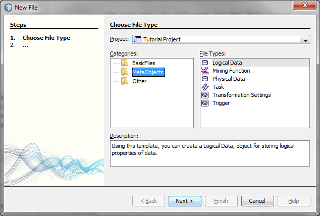
To create the desired object just select the type and press Next to specify the name for the new object. If some further customization is needed (e.g. for a metadata object) the wizard will ask the user for the necessary parameters before asking for the name.
Note
When theNew action is called for a Metadata Repository, only metadata objects can be created. The options for folders or script files will not be available.
A repository is a special type of project. It cannot be created using the New Project... action. Instead, it can only be opened using the special Open Repository... action called from the File menu or the toolbar. The Repository project is a representation of local or remote metadata repository.
After calling Open Repository... a wizard is displayed. The user has to fill in all fields with the desired values and press Finish.
More details about Metadata Repositories can be found in the Metadata Repository chapter.
When creating a metadata object there might be one additional step, in which the user is asked for a specific type of the metadata object, e.g. when creating a Mingling Function, the user has to choose from among all Mingling Function types: Classification, Approximation, Clustering etc.
When creating a Physical Data object the user is asked for a database alias and table name. More information about aliases can be found in the Aliases section.
To create a Logical Data object a Physical Data object is required. The user is asked to choose one Physical Data object from the list. The list contains only the Physical Data objects from the same repository or folder in which the new Logical Data object is being created.
More details how to create and manage metadata objects c can be found in the Metadata Repository chapter.
AdvancedMiner can recognize and edit CSV files.m The Import to Database action can be used to copy the data from a CSV file to a database table. To import data from a CSV file select the file in the Project tree, open the context menu and choose the Import to Database action. This will open the CSV import wizard.

In the first step the user is asked to provide the parameters of the imported CSV file:
Separator - the character used to separate the entries in the file. The default value is the comma, but it can be changed to any other character.
Decimal separator - the character used to separate the decimal part of floating poing values. The default value is period, but it can be changed to any other character.
Flag for header - in some CSV files the first row is used for the names of data columns. If this is the case select this option. Otherwise the first row will be treated as the first row of data.
When there is error - determines the behavior of the import procedure after an error is found in a data row. That row can be skipped and importing will continue or importing will stop at that row.
Number of rows - the types of columns are unknown, but can be discovered by looking at the data. This parameter tells the import procedure how many rows to check before determining the column type. The default option is to use all rows.

In the second step the user is asked to provide the parameters for the target:
Alias - an alias which defining the database;
Table Name - the name of the table; this can be an already existing table or a new one. The default value is the name of the imported CSV file.
Delete the old table and create a new one - this option is enabled only if the table with the given name already exists. I selected the old table is replaced witha a new one; otherwise an error message is displayed.
Metadata objects can generate code for the Gython scripting language code. To generate the code call the 'Generate Code' action on a metadata object node inside the Projects component and paste it (using CTRL+V) into the script editor.
Note
This is an experimental feature and is not guaranteed to return executable code in every case.
The Files component can be activated by selecting Menu | Window | Files or by pressing CTRL+2.
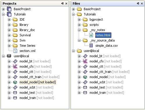
The Files component is closely related to other type of view, namely the Projects component. The Files window is just an actual physical disk structure representation of the contents of the corresponding Projects window. The physical represantation has the same tree structure as the project's root directory, however the Projects window displays only elements added by the user. These elements correspond to the elemenst visible in the 'Project_name\scripts' folder.
The Projects component recognizes numerous file types: for example: gython scripts (.py), java source (.java), html source (.html), xml source (.xml) and others. The user may also create additional folders not visible to the main project in the Project component window. To do this one has to create folders within project root directory and not inside 'scripts' subfolder.
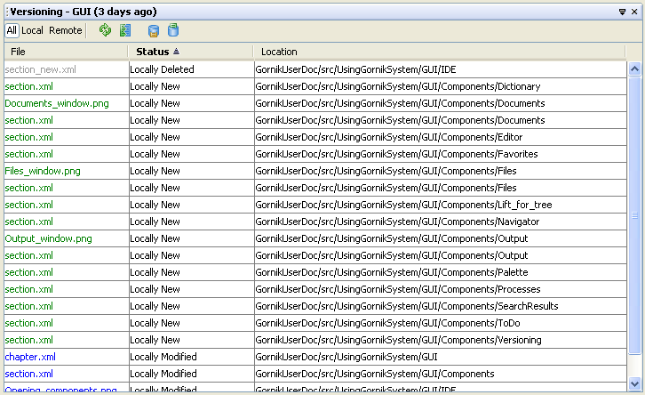
By choosing Menu | Window | Versioning the Versioning window is activated. The Versioning component is a NetBeans Platform extenstion for the CVS support. This is especially useful for large development projects. To use this component one has to run an external CVS repository server. For further information please consult your local CVS administrator or refer to the online NetBeans documentation.
The Document selector window can be activated by choosing Menu | Window | Documents... or pressing Shift+F4. The document selector is particulary usefull when to many documents are open at the same time in the main editor window.

The most recently used document in the editor window can be activated by selecting Menu | Window | Editor or pressing CTRL+0.
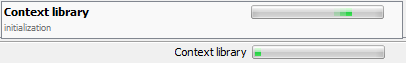
This option becomes active when at least one process (task) is being executed. The progress of running processes is visualized in progress bar located in the lower-right corner of the IDE window. When user selects Menu | Window | Processes or clicks on the process progress bar a box listing all running processes with their progress bars will appear.
The Favorites component can be activating by choosing Menu | Window | Favorites or by pressing CTRL+3. This component is a placeholder for the most frequently used folders.

Folders can be added to Favortites by right-clicking anywhere in the component area and selecting 'Add to Favorites...'. This opens a window, where the user can select the desired folder.
The Output component can be activated by choosing Menu | Window | Output or by pressing CTRL+4. The output window displays all standard stream output produced by the executed gython script. All additional information such as termination of the task or any error traceback is also printed to the output window.
For example if we run this simple logistic regression script the resulting model's parameters are displayed in the output window:

There are three actions available to the user in this window. The first
one is represented by the icon ![]() and it's used for closing all tabs opened within Output window. The next one
is
and it's used for closing all tabs opened within Output window. The next one
is ![]() and it's used for
closing all tabs exepct the active one. The last option indicated by the
and it's used for
closing all tabs exepct the active one. The last option indicated by the
![]() button is used for
toggling between continuous and tabbed output.
button is used for
toggling between continuous and tabbed output.
The Navigator component windoww is activated by choosing Menu | Window | Navigator or by pressing CTRL+7. The main function of this component is to provide graphical representation for the structure of the currently active object. Clicking on an element in the navigator windows moves the content of the editor window to the location of corresponding element and highlights it.
For example, while working with a complex gython script files it's useful to open Navigator component, which allows the content of the script to be browsed by function or class names.

Xml and html files are supported in a similar way.

The Navigator can also be used for the analysis of LIFT curves from different models or datasets.

The Palette component window is activated by choosing Menu | Window | Palette or by pressing Ctrl+Shift+8. It supports the edition of html files.
Every object has a set of simple properties associated with it, e.g. a script file has a name, file size, and modification date. The central place for displaying and modifying these properties is a component called Properties. It displays the properties of the selected object whether it is a file, a metadata object, or a set ofplatform options.
The Properties component can be activated by choosing Menu | Window | Properties, pressing the Properties button on the toolbar or by pressing CTRL+SHIFT+7.
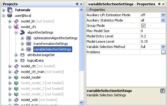
Whenever a property is selected its description is displayed at the bottom of the Properties Window.
There are three types of property editors:
simple - string and numerical properties can be edited by typing the value inside the cell on the right of the property name, or in the case of boolean values by clicking the check box.
inline - these editors are usually used for properties with a small set of possible value. They are indicated by a button with an arrow pointing down; the editor is opened inline.
custom - a custom editor is the most complex one. It opens in a separate window (for some properties a wizard may even be launched); to open the editor press the '...' button. Such editors are used e.g. for colors or fonts.


Note
When editing a property of a metadata object, the changes are made only inside the current session. To make the changes permanent or to propagate it to the Metadata Repository the object must be saved.
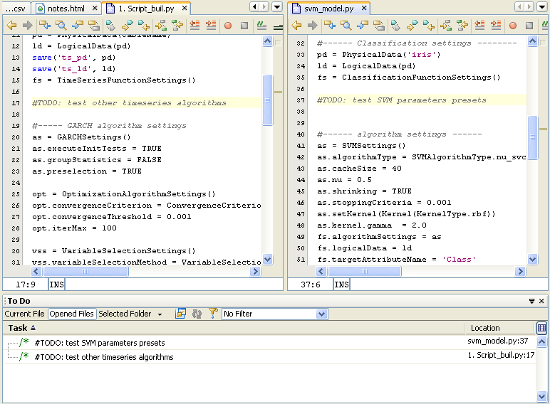
The Tasks component window is activated By choosing Menu | Window | Tasks or by pressing CTRL+6. The Tasks window is a standard NetBeans platform extension and is used by developers for indicating pending tasks by placing "#TODO" marks in source code files.
The Services component is similar in structure to the Projects component. It is used for navigating through dynamic elements of AdvancedMiner: managing database connections, browsing database tables and running processes.
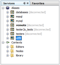
An alias is a shortcut to the properties of database connection that can be used in AdvancedMiner. Aliases are global and can be used whenever a connection to a database is required: in a script, when creating Physical Data or importing CSV files. Thanks to this infrastructure, there is no need to input all the properties of the connection when they are needed, instead it suffices to provide the name of the appropriate alias.
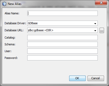
To create a new alias call the 'Add alias' action for the Aliases node. This will open the new alias wizard.
If the alias name is left empty the database URL will be used instead. To set the default alias choose an alias from the Services | Aliases, then right-click on the alias and then call the Set As Default action from the contex menu.

To delete an alias call the 'Delete' action for the alias node.
Note
An alias itself is not a database connection, it is only a reference to the parameters which make the connection possible. The actual connection is established by the infrastructure that uses the alias i.e. scirpt interpreter or Physical Data creator.
Whenever a process is running in AdvancedMiner User's Scope, it can be found in the Processes subtree. User's scope is restricted to the local client, which is basically the AdvancedMiner IDE, and remote servers to which the user is connected.

The Processes node is used for representing local runnung scripts. It displays only the name of the script. The only available action is 'Terminate', which sends the termination signal to safely finish the running script.
The progress of running processes is displayed in the progress bar located in the lower-right corner of the IDE window. The progress bar displays the information about the state of the corresponding process: progress in percentage points, the iteration number or 'undetermined' if the process does not support progress reporting. The 'Terminate' action is also available from the progress bar's context menu.

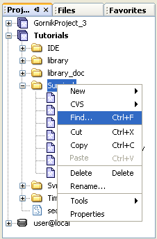
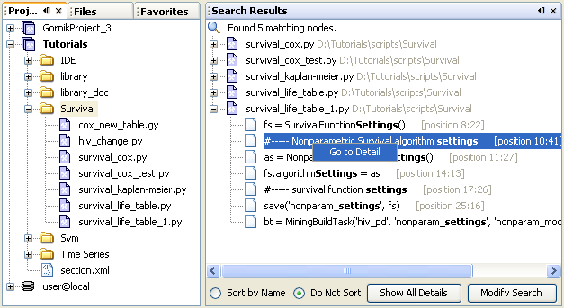
The Search Resulrs is activated by choosing Menu | Window | Search Results or by pressing CTRL+0. This component displays the results of text searches performed on files from Projectd, Files or Favorites views. The simplest way to do text search is to right-click on the folder in the Project window and then select "Find" in the contex menu.

Object editors are used to change additional properties of objects, which are not available in the Properties Window
This editor is used for all sets of attributes, which can be
identified by the ![]() icon.
Each attribute from the set has a unique identifier for
the property across all the property sets.
icon.
Each attribute from the set has a unique identifier for
the property across all the property sets.
More sets edited together inside a single instance of the editor. To add a new object to an already opened editor just drag the AttributesSet object to the editor. New columns representing the properties of this new set will be created. New rows will be added for attributes which did not appear in previously loaded sets.
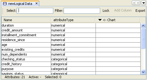
The figure below presents an editor window with Classification Function Settings for logistic regression model together with physical data used for model building. Having these two objects opend simultaneously one may properly adjust the 'usage' of an attribte using simple statistics information from the physical data contents ( like 'Null(%)' , 'Mean', 'Distinct' ). Additionally, the Navigator component helps in selecting particular statistics to be shown.

To modify attributes an inline editor is used (identical to the one in the Properties component). When more than one attribute is selected, clicking with the left mouse button opens an editor which will change values in all selected attributes.
When editing AttriubteUsageSet the group column is available. The information that some attributes belong to one group can be used for optimization of some algorithms e.g. the binarization transformation creates new attribute for every category of the transformed attribute, but those new attributes are representations of one single attribute. That information can be used later by variable selection algorithms.
This editor is used for charts representing the quality of
classification models:
Lift chart (LiftAnalysis object
![]() )
and ROC curve (RocAnalysis
)
and ROC curve (RocAnalysis ![]() ).
The most important part is the Chart
component. The Navigator and
Properties
components are also used.
).
The most important part is the Chart
component. The Navigator and
Properties
components are also used.
The active elements of the Chart are:
legend - can be dragged around the chart; when an element from the legend is selected, the Lift and ROC lines represented by this element are highlighted;
Lift or ROC line - this is equivalent to selecting an element from the legend;
chart background - the properties of the whole chart can be edited in the Properties component, e.g. cumulated or not cumulated lift, lift or probability, discrete or continuous.


The Chart Editor may also be used for presenting other model quality measures such as Kolmogorov-Smirnov statistic.

The Navigator orders all chart elements into a simple tree. The root of this tree represents the whole chart and every descendant a single plot.
A new plot line can be added to the chart by dragging a LiftAnalysis/ROCAnalysis node from the Projects to the opened chart window. To remove the plot from the chart call the Delete action for the appropriate node in the Navigator. To modify the properties of the line (color, width, line type) choose th Properties action from the context menu of the node representing line.
Note
LiftAnalysis objects, ROCAnalysis and K-SAnalysis objects cannot be mixed together on the same chart.
More information about LiftAnalysis, ROCAnalysis and K-SAnalysis can be found in the Classification Model Testing chapter.
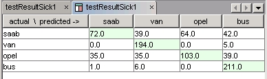
The Confusion Matrix Editor is a component for representing the
Confusion Matrix objects, represented by the
![]() icon. Confusion Matrix
is a compact way of displaying how the model classified the examples.
Some additional statistics can be computed on the basis of the Confusion Matrix.
These statistics are accessed using the same editor
in the targetAnaysis node in the classification test
task results object.
icon. Confusion Matrix
is a compact way of displaying how the model classified the examples.
Some additional statistics can be computed on the basis of the Confusion Matrix.
These statistics are accessed using the same editor
in the targetAnaysis node in the classification test
task results object.
Note
It is possible for a cell of the Confusion Matrix to have the value NaN. This means that there was no data available to compute the statistic. It can appear in target analysis.
More information about Confusion Matrix can be found in the Classification Model Testing chapter.
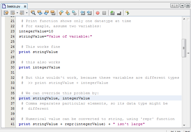
The script editor is designed to make the editing of a scripts as simple as possible. It supports features like:
syntax highlighting,
auto indentation,
code completion (experimental),
block commenting/uncommenting,
bracket matching,
bookmarks.
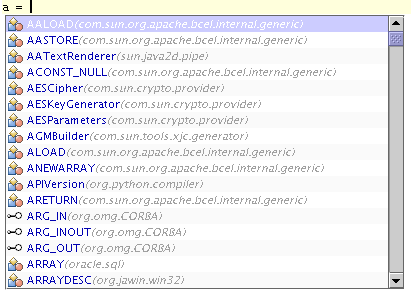
The script editor has code completion capability. This streamlines code writing and makes the work with system more comfortable. Analysts are relieved of the necessity of keeping in mind long names of functions, classes, packages, modules etc. Code completion is activated with the 'Ctrl + Space' key combination. After activation of code completion, a box with a list of proposed names shows up at the current cursor location. The code completion box also contains prompts connected with imports defined in script. Code completion will not guarantee the correctness of the created script.
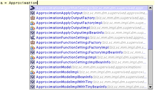
The list of proposition is reduced as user types letters (now the list consists of the found matches):
Code completion - short how to:
After pressing the 'Enter' key the currently typed name is completed with the selected position.
The list can be browsed using the Page Up, Page Down, Home, End keys or with the mouse.
The 'Tab' key completes the name with the longest common prefix.
The list elements are arranged alphabetically in each group (Java language elements such as: metamodel, packages, Gython language elements, database content).
The order of the displayed groups depends on context: in an SQL block the top of the list contains proposed names connected with database content, beyond SQL blocks those elements are located at the end of list.
The order of elements in a list is determined by categories: Gython preceeds Java (ordering: method,class, package/module)
Code completion for Java and Gython supports the displaying of:
packages name,
classes,
interfaces
modules.
The proposed names include all elements of metamodel office support packages, distribution libraries, statistical tests and other classess, and interfaces included in classpath. The full list of found and compiled Gython modules is also displayed. As can be seen in the figure below, icons are displayed to the left of the code completion elements, and names of packages are to the right. Code completion also supports completion for packages (after typing the package name followed by a dot the elements of the package are displayed.
Icons can be used to identify the type of the element (respectively for elements connected with Java and Gython).

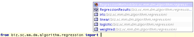
Completion for 'import' and 'import form' keywords is also supported:
Code completion supports writing scripts than work on databases. In this case the list box contains:
packages names,
aliases,
table names,
views
attributes

The elements are displayed according to the following schema: Aliases are displayed first (ex. 'default alias'), next the tables from the first alias (ex. 'a$a') and their attributes (ex. 'a','b'). Views are placed below the table list in similar way (view name, view attributes).
Note
Only activated elements will be displayed, e.g. to see table names it is necessary to expand the alias node, to see the variable names it is necessary to expand the table node.
The documentation browser for selected element shows up when browsing the code completion list. This feature helps to access the documentation describing the usage of the current element without opening a separate window

The documentation window can be navigated in the same way as any Internet browser.
Clicking on the ![]() icon opens
a tab with the documentation documentation.
icon opens
a tab with the documentation documentation.